
A Car consists a motor to give it forward and backward motion and its extended version would consist of another function of left and right motion which also require second motor. Therefore a car can have a minimum of Four Functions viz. Forward(Turbo), Backward, Left and right motion. The forward motion of the car is also termed as turbo because in this motion the driver takes full advantage of car as car lover already know.The car motor is powered by a dry 12v or 6v battery so that maximum torque and speed combination is developed in the motor.If the car is wired then it is easy to make it and run it but you have to move with the car also and there is always a chance of wear and tear of the car wire control of the car.The wired car range of running forward is less as compared to wireless car.It cannot move to farther distance like wireless car ca do. Hence there is a need of having wireless remote control car but it market cost is quite large, why not make your own cheaper wireless remote control car with some electronics knowledge and component available in the market are cheaper then the actual remote control car. First of all you should have the knowledge of various electronics components like transmitter and receiver module. In india 315 Mhz and 433 Mhz band is allowed as general purpose frequency band for common people use.Hence transmitter and receiver module are available in this range of frequency bands.The transmitter and receiver module are nothing but premade pcbs by using different amplifier stages and op amp ic and totally depend upon manufacturer.The transmitter module is usually smaller in size than receiver module and have Four terminals or pins viz. Vcc , Data in, Ground and Antenna.The Receiver Module also has four main terminals Vcc, Ground, Antenna and Data out.

Transmitter module (left) and Receiver Module (right)
They work on ASK (Amplitude shifting Keying) Modulation.It is a type of digital modulation. ASK is a form of Amplitude modulation which represent digital data as variation in amplitude of a carrier wave.The amplitude of the carrier changes according to the digital baseband signal.

I recommend you to study the transmitter and receiver module datasheet once only to know about its working and its rating.You can buy the modules either from eBay or from Delhi chandni-chook electronics market (for indians).I have bought three pair of modules worth Rs.525 (each Rs.175), from Shop no-594.
Now the next thing you must know about is the Encoder HT12E and Decoder HT12D ic which are most important part of the RF circuit.The encoder ic is the ic for taking input through it four pins viz. 10,11,12 and 13 pins of the ic These pins are the data pins and denoted by AD8 ,AD9, AD10 ,AD11.These pins have to be connected to ground through push buttons.The Address pins 1 to 8 is used to provide the address of the transmitter and the Decoder ic must have same address so as to interact with the transmitter .The encoder in simple words is the multiplexer which encodes or multiplexes the signal along the same band of channel.It increases the total capacity of the channel band.They are available as 4 bit encoder.Here is the pin diagram of HT12E with transmitter module. The Dout is the four bit data with the 8 bit address multiplexed with it.The encoded signal is given to transmitter module Data in pin for the transmission the the ASK signal.

Now let us talk about HT12D ic.It is a decoder ic and is used to demultiplex the received data from receiver module.The HT12D ic does the reverse of HT12E ic.It decodes the received data into useful four bit information for remote control application.The decoder address pin connection must be in same configuration as that of encoder ic,otherwise it may not decode the received data into useful information.Here is the pin diagram of HT12D ic with Receiver module.

The receiver module receives the signal and give it to the Din pin of the decoder ic.The decoder ic decodes the data given and provide the four bit useful data at pin no. 10,11,12,13.Which is used for remote control application.
The data is serially transmitted and received.
Now the next ic you must be familiar of is the Quadruple Half H-Drivers Ic which is the LD293D Ic.It has four H-bridge Drivers and is used in controlling the forward and backward motion of motors.You Must read the datasheet of all the ICs discussed in the article.Here is the pin diagram with application.


Th Driver Ic has 16 pins in which pin no. 4,5,12,13 are ground of the Ic and pin no.16 is the ic supply voltage and Pin no.8 is the motor supply voltage.Pin no. 3 and 6 are enable for the motor bridge circuit and must be connected to the +5 volt supply so as to enable the H-bridge.Pin no. 3,6 and 11,14 are the output for motor terminals.Pin no.5,7 are used for controlling the forward and backward motion of the motor connected at pin no.3,6 and pin no.10,15 are used for controlling the forward and backward motion of the motor connected at pin no.11,14.
The next Ic is the 5 volt supply Ic which is LM7805 ic.It takes battery terminal voltage input greater than 7 volt and less than 36 volt And convert it into 5 volt.Here is the circuit diagram.


Now we have Enough Knowledge about the components to be used.Here is the List of components required For making the Remote control car.
:: LM7805 IC 2nos
:: LD293D IC 1nos
:: HT12D IC 1nos
:: HT12E IC 1nos
::315Mhz Transmitter and receiver Module Pair 1nos
::9v dry battery 2nos
::Copper clad board 50cm by 50cm
::Cardboard 50cm by 50cm
::DC Motors 2nos
::Gears As requred
::Feviquick 10ml
::Ferric chloride 30gms
::water in plastic bucket
::Hand Drill
::Express Pcb software installed on your computer.
::Magazine paper
::Laser printer
Here is the block diagram of the remote control car --

The motor 1 is the steering motor and motor 2 is the engine power motor.I have used various stuff to design the hardware of the car and it will be discussed later.
Now First of all Make the following circuit on Express pcb and then justify all the pin connection according to the given circuit diagram--

For making the pcb layout you must be familiar with express pcb software.It is the software used for designing the pcb layouts and it is freeware, you can download it from Here.It has two parts one is the Express SCH and other is Express PCB.The former is used to make the circuit diagram and then it is linked to the latter which is used for designing the pcb layout.If you don't want to make the circuit diagram in SCH then no matter you have to justify the layout in PCB design.
Now print the layout on a butter paper or a magazine paper with the help of laser printer.If you don't have a laser printer then most of the photo copy shop have the facility of laser printing then you must go there with the .xps file in flash drive and have the printed layout on butter paper or magazine paper.
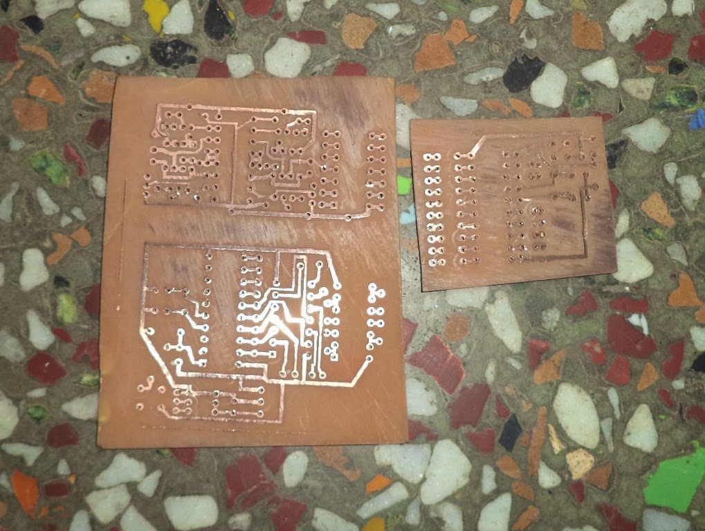
Now you should cut the copper clad board with the help of a cutter of the size of layout and then cleane the copper side of the board with the help of scotch brite pad.Now further clean it with dry cloth and then put the printed side of paper on the copper side of board touching it. Now pre heat the cloth iron and then apply the heat and pressure to the board and paper using the iron for 10 minutes.You will observe after 10 minutes the paper has sticked to the board, now wash the board paper using water,you will see that the layout has transfered to the board and then dip it into the ferric chloride solution for 15 minutes. Now take out the board after 15 minutes and wash it using water.Now again wash it using thinner or kerosene oil, you will see that the pcb is ready to be drilled. Now using hand drill or stand still drill wit 1mm bit pierce the holes at appropriate places on the board for mounting the components.
Now according to the circuit diagram put appropriate components on their respective places and shoulder them using iron and paste and shoulder.Add the power supply and fix all the components pcbs and car hardware and your car is ready to use.
I have used the Lm7805, LD293D from Texas instruments and ST microelectronics.HT12E and HT12D from Holtek.
For making the car hardware or chasis you must cut the appropriate size of the card board and the using the pads from telecoms companies which come with the SIM card, make all the support for the wheels and design the steering system as shown in fig. and then fit the motor and gears train to get more torque. And make all the connections,Your card is ready to run.
Here are some snapshots of car.


No comments:
Post a Comment